First of all, we need to understand the concept that the power supply node of the SS880X and SS881X internal systems has only one (VDD). This is determined by the power architecture of the two ICs. As shown in Figure 1, whether it is powered from SPWR/VKEY, VIN or VDD, the power supply must eventually pass through VDD to supply the entire system.
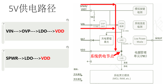
Figure 1
As shown in Figure 2, the direction shown by the arrow is only the charge path from VKEY and VIN to BAT, and there is no path from BAT to VDD. We connect the battery to the BAT pin of the chip in order to charge the battery using the chip's charge management module (charger). Instead of powering the system with batteries.
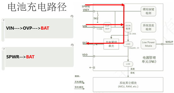
Figure 2
So how to supply the system with batteries, there are two options:
Solution 1:
As shown in Figure 3, BAT and VDD are connected together, there is no diode isolation, and VDD voltage = BAT voltage. The normal operation condition of the system is VDD voltage ≥ system minimum operating voltage LVR (Low Voltage Reset). Assuming that LVR is set to 2.8V and the battery is in an over-discharge state of 1V, neither the system nor the charger will work. If you want the system to work, you can only use DC5V power supply, due to the battery overdischarge, the voltage of DC5V through the LDO is directly pulled down by the battery, resulting in the system can not work immediately.
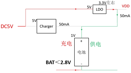
Figure 3
As shown in Figure 4, the system does not work until the battery voltage is charged to 2.8V by LDO, and the system works before the charger is turned on. When 2.8V≤ BAT <3.3V, the charger and LDO charge the battery together, and the LDO also outputs part of the power supply to the system, and BAT will quickly be charged above 3.3V.
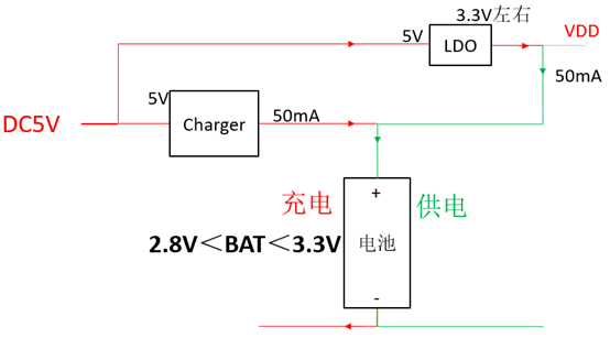
Figure 4
As shown in Figure 5, when BAT > 3.3V, the LDO is no longer working, but is powered by the charger.
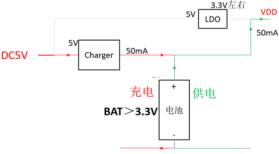
Figure 5
Solution 1 saves one diode, but there are two problems:
1、It may take a few minutes for the battery to charge from 1V to 2.8V. You cannot see the UI immediately when DC5V is connected.
2、If the system is powered by wireless charge. The handshake time of wireless charge TX and RX (881X is RX controller) is only about 60ms, after the battery is over-discharged, the system can not work within 60ms and handshake with TX successfully, after 60ms TX will interrupt the wireless charge, resulting in wireless charge failure.
Solution 2:
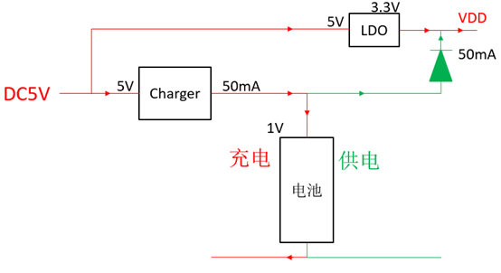
Figure 6
As shown in Figure 6, the series diode isolation between BAT and VDD, DC5V can be used to power the system normally through the LDO. Because, if the battery is over-discharged, BAT < VDD, the diode will not turn on, and the VDD will not be pulled low by the battery like in Solution 1. Therefore, it can also operate normally until the battery voltage is charged to the system minimum operating voltage LVR (LVR). There will be no problem in solution 1, and the disadvantage is that one more diode is used.
Original article, Please mark the attribution when reprinting. SINHMICRO,www.sinhmicro.com。